computer motherboard parts and functions pdf
Computer Motherboard⁚ An Overview
The motherboard, a crucial circuit board, connects and enables communication between a computer’s components. It houses the CPU, RAM, and expansion slots, facilitating seamless system operation. Understanding its function is key to PC maintenance and upgrades.
The computer motherboard, often called the mainboard or system board, serves as the central printed circuit board (PCB) within a computer. It’s the foundation upon which all other components are built and connected. Think of it as the central nervous system of your computer, facilitating communication between the CPU, memory, storage devices, and peripherals. Its design varies based on size (form factor) and intended use, impacting available expansion options and overall system capabilities. Understanding the motherboard is crucial for building, upgrading, or troubleshooting a computer system; This fundamental component is essential for any digital device, large or small.
The Motherboard’s Central Role
The motherboard’s primary function is to act as the central communication hub for all computer components. It provides the physical pathways and electrical connections necessary for data exchange between the CPU, RAM, storage devices, and expansion cards. This integrated design allows for efficient data processing and system operation. The motherboard also manages power distribution to these components via various connectors and power phases. Its design directly impacts a computer’s performance and expandability. Essentially, without a functioning motherboard, the various computer parts cannot communicate and the system remains inoperable. It’s the linchpin of the entire system.

Key Components and Their Functions
This section details essential motherboard components⁚ the CPU, RAM, and expansion slots, explaining their individual roles in overall system functionality and performance.
Central Processing Unit (CPU) and Socket
The CPU, or central processing unit, is the computer’s “brain,” executing instructions and performing calculations. The CPU socket on the motherboard is the physical interface, a precisely designed connector that holds the CPU in place. Different CPUs require specific sockets; matching CPU and socket is crucial for compatibility. The socket ensures reliable electrical connection, allowing for efficient data transfer between the CPU and other components. Improper installation can damage both the CPU and motherboard. Choosing the right CPU and ensuring correct installation are vital for optimal system performance.
Random Access Memory (RAM) and Slots
RAM, or random access memory, provides fast, temporary storage for data the CPU actively uses. The motherboard features RAM slots, specifically designed connectors where RAM modules are installed. RAM speed and capacity significantly impact system performance; faster RAM allows for quicker data access, improving responsiveness. The number of RAM slots determines how much RAM can be installed. Different RAM types exist (DDR3, DDR4, DDR5), each requiring a compatible slot. Incorrect RAM installation can lead to system instability or failure. Matching RAM type and capacity to system requirements is essential for optimal performance.
Expansion Slots⁚ PCIe and Others
Expansion slots extend the motherboard’s functionality, allowing for the addition of peripherals and upgrade components. The most common type is PCIe (Peripheral Component Interconnect Express), offering various sizes and speeds (x1, x4, x8, x16). PCIe slots accommodate graphics cards, sound cards, network adapters, and other expansion cards. Older motherboards may also include legacy slots like PCI or AGP, though these are less common now. The physical size and type of expansion slot must match the expansion card; using an incompatible card could damage the system. The placement and number of expansion slots vary significantly depending on the motherboard model and its intended use.

Power and Connectivity
The motherboard manages power distribution and connections. It receives power from the PSU and provides power to other components via various connectors. External ports provide interfaces for peripherals, enabling user interaction and data transfer.
Power Supply Connectors
The motherboard utilizes several connectors to draw power from the computer’s power supply unit (PSU). The primary connector is typically a 24-pin ATX connector, providing the main power rail for the motherboard’s circuitry. An additional 4-pin or 8-pin EPS connector supplies power directly to the CPU, crucial for demanding processors. These connectors are standardized, ensuring compatibility across different PSU and motherboard brands. Incorrect connection can lead to system failure or damage. Always consult your motherboard manual to ensure proper and secure connection of the PSU cables to their designated connectors on the motherboard for optimal performance and stability.
Internal Connectors⁚ SATA, etc.
Internal connectors on the motherboard facilitate communication with internal storage devices and other components. SATA (Serial ATA) connectors are prevalent, providing high-speed data transfer for hard disk drives (HDDs) and solid-state drives (SSDs). These connectors are typically found in groups, allowing for multiple storage devices. Other internal connectors might include those for case fans, enabling motherboard control over fan speeds. M.2 slots provide high-speed connectivity for NVMe SSDs, offering significantly faster data transfer compared to SATA. The specific internal connectors available vary depending on the motherboard model and its capabilities. Understanding these connectors is crucial for installing and connecting internal peripherals correctly.
External Ports⁚ USB, Audio, etc.
External ports on the motherboard provide connection points for peripheral devices. USB (Universal Serial Bus) ports are ubiquitous, offering versatile connectivity for keyboards, mice, printers, and external storage. Different USB versions (e.g., USB 3.0, USB-C) offer varying data transfer speeds. Audio ports (line-in, line-out, microphone) enable sound input and output, connecting speakers, headsets, and microphones. Other common external ports may include Ethernet (RJ-45) for network connectivity, DisplayPort or HDMI for video output to monitors, and legacy ports like PS/2 for older keyboards and mice. The arrangement and types of external ports vary greatly between motherboards, influencing the range of peripherals a user can connect. Identifying and understanding these ports is essential for connecting external devices to the computer.
BIOS and Chipset
The BIOS (Basic Input/Output System) chip manages the boot process, while the chipset (northbridge and southbridge) controls communication between the CPU, RAM, and other components. They are fundamental to system operation.
The BIOS Chip⁚ Firmware and Boot Process
The BIOS chip, containing firmware, is essential for initiating the computer’s boot sequence. This small but powerful component performs a Power-On Self-Test (POST) upon startup, checking hardware functionality. If errors are detected, error codes are displayed, providing valuable diagnostic information. Successful POST allows the BIOS to locate and load the operating system from a storage device (hard drive, SSD, etc.), transferring control and enabling the system to function. The BIOS’s role in the boot process is critical; without it, the system wouldn’t start.
Northbridge and Southbridge (or Chipset)
Historically, the chipset consisted of the northbridge and southbridge, acting as crucial communication hubs on the motherboard. The northbridge, a high-speed component, facilitated communication between the CPU, RAM, and the graphics card (if integrated). The southbridge, operating at a lower speed, managed slower peripherals such as USB ports, storage devices (via SATA), and expansion slots like PCI. Modern motherboards often integrate these functions onto a single chip, simplifying the architecture. Regardless of the design, the chipset remains vital for coordinating data flow between the CPU and other motherboard components, ensuring smooth system operation.
Motherboard Form Factors
Motherboard sizes, like ATX, Micro-ATX, and Mini-ITX, impact case compatibility and expansion capabilities. Choosing the right form factor depends on your system’s size and upgrade needs.
ATX, Micro-ATX, and Mini-ITX
ATX, the standard full-size motherboard, offers ample expansion slots and space for components. Micro-ATX, a smaller version, retains many features but with reduced expansion options, suitable for compact systems. Mini-ITX, the smallest form factor, prioritizes space-saving design, ideal for small-form-factor PCs or HTPCs, sacrificing expansion potential for compactness. The choice depends on available case space, desired expansion capabilities, and the intended use of the computer system. Consider your needs regarding expansion slots (PCIe, etc.) and the number of storage devices before selecting a form factor.
Choosing the Right Form Factor
Selecting the appropriate motherboard form factor hinges on several key considerations. Firstly, assess the physical dimensions of your computer case; ensure compatibility to avoid incompatibility issues. Secondly, evaluate your expansion needs; ATX provides maximum flexibility, while Micro-ATX and Mini-ITX offer limitations. Consider the number of expansion cards (graphics cards, sound cards, etc.) you intend to install. Finally, contemplate your budget; larger boards usually cost more. Matching the form factor to your case and expansion requirements is paramount for a successful build, maximizing functionality within your chosen configuration.
Understanding Motherboard Diagrams
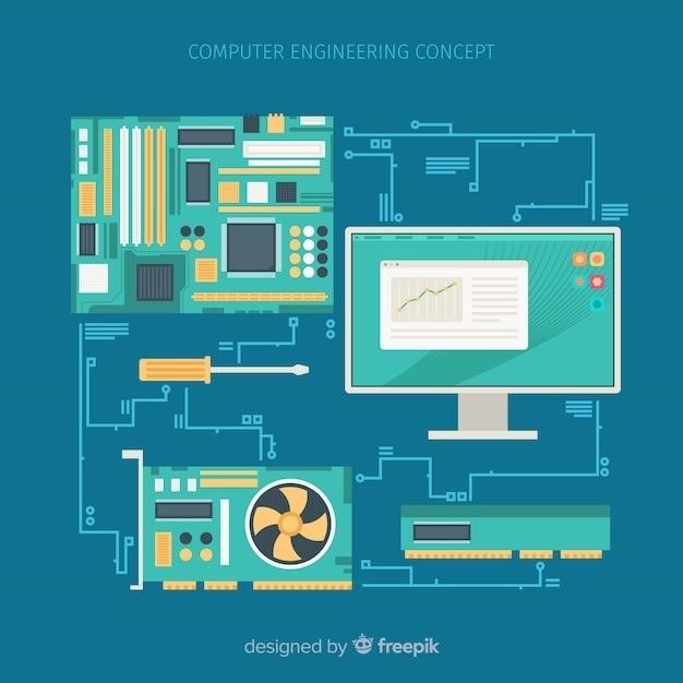
Motherboard diagrams are essential for identifying components and their connections. They simplify troubleshooting and upgrades by visually representing the system’s layout and interconnectivity.
Interpreting Schematics and Layouts
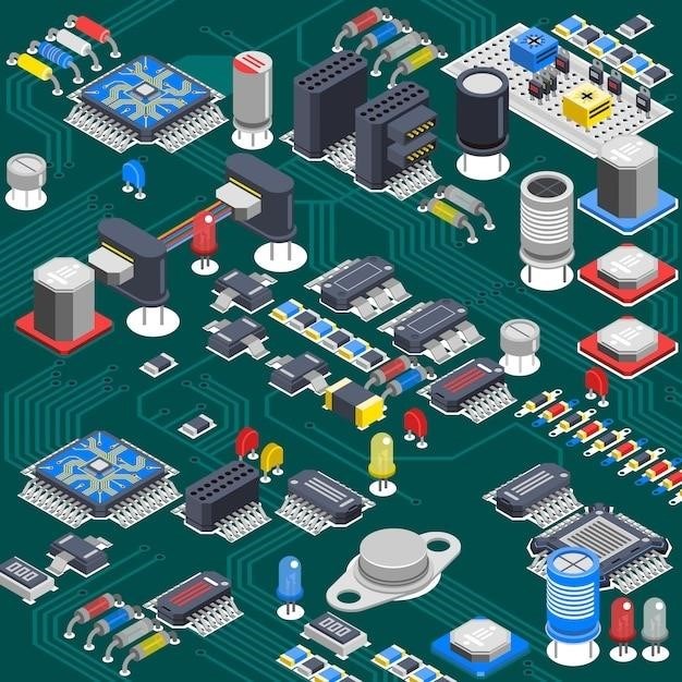
Understanding motherboard schematics and layouts requires familiarity with common symbols and component designations. These diagrams use standardized representations of parts like CPUs, RAM slots, and expansion slots, showing their physical placement and connections. Careful examination reveals the pathways for data and power flow, crucial for troubleshooting hardware issues. Different manufacturers might use slightly varying notations, so consulting the specific motherboard’s manual is always recommended. Learning to interpret these visual representations is a valuable skill for anyone building, upgrading, or repairing computers. The diagrams show how components interconnect, aiding in understanding data flow and power distribution within the system. Successfully deciphering these diagrams empowers users to confidently diagnose and fix problems, making them invaluable tools for computer enthusiasts and technicians alike. Mastering this skill enhances both troubleshooting and upgrade capabilities.
Identifying Components in Diagrams
Motherboard diagrams utilize symbols and labels to represent various components. The CPU socket, usually a prominent feature, is easily identified. RAM slots are typically grouped together and clearly marked. Expansion slots, such as PCIe, are also readily visible and often color-coded. Power connectors, both for the main power supply and auxiliary power, are clearly shown. The BIOS chip, a small integrated circuit, might be labeled or easily located near the CPU socket. Other components like SATA connectors, USB headers, and audio jacks are identified by their unique symbols. Careful study of the diagram’s legend or key is essential for accurate component identification. Manufacturers may use slightly different representations, so consulting the motherboard’s manual offers further clarity. Accurate identification is crucial for troubleshooting, upgrades, and even basic understanding of the motherboard’s functionality.