3 way switch wiring diagram pdf
Understanding 3-Way Switch Wiring Diagrams
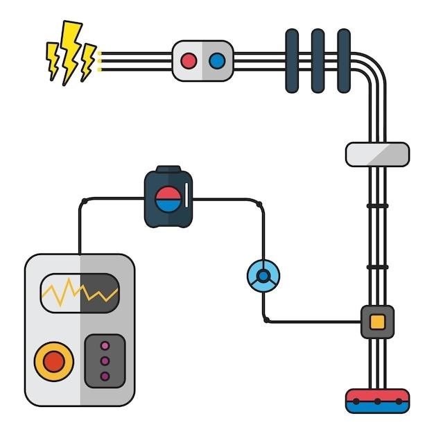
Three-way switch wiring diagrams illustrate how two switches control a single light fixture. Power enters one switch, travels through traveler wires to the second switch, and finally reaches the light. Multiple configurations exist depending on power entry point and light placement. Understanding these diagrams simplifies installation and troubleshooting.
Power Source Entry Point Variations
The power source’s entry point significantly impacts a 3-way switch wiring diagram. One common configuration shows power entering the first switch box, then continuing to the light fixture and the second switch. Alternatively, power might directly feed the light, with switches controlling the circuit’s continuity. A third variation involves power entering the second switch, then flowing through the traveler wires to the first switch and finally to the light. Each variation necessitates a different wiring approach, emphasizing the importance of accurate diagram interpretation. Detailed diagrams often illustrate these variations, clarifying wire connections and switch positions. Careful observation of the power entry point is crucial for successful 3-way switch installation and troubleshooting. Incorrect identification can lead to malfunctioning switches or electrical hazards. Consult reliable diagrams for your specific setup to avoid issues.
Different Wiring Configurations for Multiple Lights
Controlling multiple lights with a pair of 3-way switches introduces additional wiring complexities. Simple diagrams often show a single light fixture, but expanding to two or more lights requires careful planning. One approach involves wiring each light individually, connecting each to both switches through separate traveler wires and common connections. Alternatively, lights can be grouped, with a single set of traveler wires controlling multiple fixtures simultaneously. This approach simplifies wiring but requires all lights to operate in unison. The choice depends on desired functionality. Detailed diagrams are essential, clearly indicating the connections for each light and switch. Incorrect wiring can lead to lights not functioning correctly, and in some cases, electrical hazards. Consult reputable sources and diagrams to ensure a safe and functional installation, especially for more complex setups involving numerous lights and switches.
Troubleshooting Common 3-Way Switch Problems
Troubleshooting 3-way switch issues often begins with verifying power supply to the circuit. A tripped breaker or faulty wiring in the power source can prevent the switches from working at all. Next, check the switches themselves; loose wires or internal switch failures are common culprits. Examine the connections carefully, ensuring all wires are securely fastened and correctly matched to the terminals. Use a voltage tester to confirm power is reaching the switches and the light fixture; this helps isolate whether the problem lies in the wiring or the switches themselves. If only one switch functions, a faulty switch or incorrect wiring between the switches is the likely issue. A short circuit can cause a breaker to trip, so carefully check all connections for any bare wires touching. Refer to wiring diagrams to verify proper configuration and identify any potential errors. Persistent issues may require professional electrical assistance.

Accessing 3-Way Switch Wiring Diagrams in PDF Format
Numerous online resources offer downloadable 3-way switch wiring diagrams in PDF format. Websites, including Building in California and Pinterest, provide helpful visual aids and detailed instructions. These PDFs simplify understanding and installation.
Locating Diagrams Online
Finding 3-way switch wiring diagrams online is surprisingly straightforward. A simple web search using keywords like “3-way switch wiring diagram PDF” yields numerous results. Many electrical supply websites offer these diagrams as part of their product support or informational resources. These diagrams often come in various formats, including clear illustrations and step-by-step instructions. Furthermore, dedicated electrical forums and websites often feature discussions and user-submitted diagrams, which provide diverse perspectives and troubleshooting advice. Remember to carefully verify the source’s reliability and the diagram’s accuracy before using it for any electrical work. Always consult qualified electricians for complex installations or if you are unsure about any aspect of the wiring process. Safety should always be your top priority. Don’t hesitate to seek expert assistance to ensure the correct and safe installation of your 3-way switch.
Utilizing Resources like Building in California
Websites dedicated to building codes and regulations, such as “Building in California,” can be invaluable resources for finding detailed 3-way switch wiring diagrams. These sites often provide diagrams that comply with local and national electrical codes, ensuring your installation is safe and legal. The diagrams found on such sites usually incorporate specific details relevant to regional building practices, offering a level of precision not always present in generic online diagrams. Furthermore, these resources may provide supplementary materials, like explanations of the diagrams and related electrical concepts. This contextual information can significantly aid understanding and proper implementation. However, remember that these resources should complement, not replace, the guidance of a qualified electrician. Always prioritize safety and compliance by ensuring your work adheres to all relevant building codes and regulations. If in doubt, seek professional help.
Exploring Pinterest and Other Visual Platforms
Platforms like Pinterest offer a wealth of visually-rich content, including numerous 3-way switch wiring diagrams. Searching for terms like “3-way switch wiring diagram PDF” or “electrical wiring diagrams” will yield a variety of results, often showing different wiring configurations and approaches. While Pinterest and similar platforms provide readily accessible diagrams, it’s crucial to exercise caution. Verify the source’s credibility and accuracy before using any diagram. Many user-generated diagrams may lack the precision and adherence to electrical codes found in professional resources. Always cross-reference information from multiple sources and, if uncertain about any aspect of the wiring, consult a qualified electrician. Remember, incorrect wiring can lead to electrical hazards; prioritize safety and accuracy above all else when working with electrical circuits; Utilize these visual platforms as supplementary tools to enhance your understanding, but not as the sole basis for your wiring project.

Detailed Wiring Diagrams and Explanations
This section provides comprehensive 3-way switch wiring diagrams, illustrating various configurations and clarifying the function of each wire. Clear explanations accompany each diagram for easier understanding.
Standard 3-Way Switch Wiring Diagram
The fundamental 3-way switch wiring diagram typically shows a power source connected to the common terminal of one switch. From there, two “traveler” wires carry the power to the other switch. These traveler wires connect to the corresponding traveler terminals on both switches. The common terminal of the second switch is then connected to the light fixture, completing the circuit. The diagram will clearly show the hot, neutral, and ground wires, along with their connections to the switches and the light. A neutral wire runs directly from the power source to the light, providing a complete path for the current. Understanding this basic layout is crucial before moving on to more complex configurations involving multiple lights or additional switches.
Variations exist depending on where the power source enters the circuit—either at the first switch or directly to the light fixture. The placement of the power source influences the wiring, but the core principle of using traveler wires to control the light from two locations remains consistent. Accurate diagrams are essential for safe and effective installation. Always consult a qualified electrician if you are unsure about any aspect of the wiring process.
Variations for Multiple Light Fixtures
Extending the standard 3-way switch setup to control multiple light fixtures introduces variations in wiring diagrams. One common approach involves connecting the common terminal of the second switch to a junction box. From this junction box, individual circuits branch out to each light fixture. Each light receives its own neutral wire directly from the power source for safe and independent operation. This ensures each light can be controlled independently by the switches despite being part of the same circuit. Detailed diagrams will show this branching clearly, illustrating how each light receives power and how the switches control the flow of electricity to each. This configuration allows for individual control, dimming options (with compatible fixtures), and more flexibility in lighting design. The complexity of the diagram increases proportionally to the number of lights being controlled; however, the fundamental principles of traveler wires and common terminals remain unchanged.
Another method involves using multiple sets of traveler wires, one set for each light fixture. This approach, though more complex, offers complete independent control over each fixture and is often preferred for larger installations or when precise control is paramount. Careful planning and accurate diagrams are absolutely essential for successful installation and to avoid short circuits or other electrical hazards. Remember to always consult local electrical codes and, when in doubt, seek the assistance of a qualified electrician.
Advanced Configurations⁚ Incorporating 4-Way Switches
Introducing 4-way switches into a circuit allows control of a light fixture from three or more locations. This significantly increases complexity, requiring careful attention to wiring diagrams. A 4-way switch acts as an intermediary, transferring the signal between two 3-way switches. The traveler wires now carry the signal through multiple 4-way switches before reaching the final 3-way switch connected to the light. Each 4-way switch has four terminals⁚ two common terminals and two traveler terminals. The common terminals are not connected directly to the power source; instead, they act as pass-through points for the traveler wires. The traveler wires connect the 4-way switches in series, allowing the signal to be routed to the correct switch based on the positions of all switches in the circuit. Diagrams for these configurations will be more intricate, clearly showing the connections between the 3-way switches, 4-way switches, and the light fixture. Proper grounding is crucial in these more complex setups. Incorrect wiring can lead to malfunctions or electrical hazards. Consult detailed wiring diagrams specific to your setup and always prioritize safety.
Remember, for any circuit involving multiple switches, a qualified electrician should be consulted if you are unsure of the process. Improper wiring can lead to dangerous situations including electrical fires. Always verify your work before applying power to any circuit.